
Dans cet article, il sera abordé :
- le routage inter-vlan sur un switch (cisco 3560) ;
- les ACL et association sur VLAN (VACL).
I Routage inter-vlan avec un switch
I.1 Avant de commencer
Ci dessous le schéma de travail :
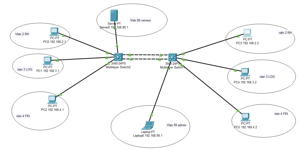
Pour chaque switch avoir les vlan suivants :
Switch1#show vlan brief

VLAN Name                             Status    Ports
---- -------------------------------- --------- -------------------------------
1    default                          active
2    RH                               active    Fa0/2
3    LOG                              active    Fa0/3
4    FIN                              active    Fa0/4
20   inactif                          active    Fa0/1, Fa0/5, Fa0/6, Fa0/7
                                                Fa0/8, Fa0/9, Fa0/10, Fa0/11
                                                Fa0/12, Fa0/13, Fa0/14, Fa0/15
                                                Fa0/16, Fa0/17, Fa0/18, Fa0/19
                                                Fa0/21, Fa0/22, Fa0/23
80   serveur                          active    Fa0/20
99   Admin                            active    Fa0/24
1002 fddi-default                     active
1003 token-ring-default               active
1004 fddinet-default                  active
1005 trnet-default                    active
Les 2 ports gigabits sont en mode trunk et aggrégés comme suit :
Switch1#show etherchannel port-channel
                Channel-group listing:
                ----------------------

Group: 1
----------
                Port-channels in the group:
                ---------------------------

Port-channel: Po1    (Primary Aggregator)
------------

Age of the Port-channel   = 00d:00h:03m:24s
Logical slot/port   = 2/1       Number of ports = 2
GC                  = 0x00000000      HotStandBy port = null
Port state          = Port-channel
Protocol            =   LACP
Port Security       = Disabled

Ports in the Port-channel:

Index   Load   Port     EC state        No of bits
------+------+------+------------------+-----------
  0     00     Gig0/2   Active             0
  0     00     Gig0/1   Active             0
Time since last port bundled:    00d:00h:03m:11s    Gig0/1
II.2 Interface virtuelle de Vlan
Il faut dans un premier temps créer des interfaces de Vlan sur un deux switch (pas les deux).
Switch1#conf t
Switch1(config)#interface vlan 2
Switch1(config-if)#ip address 192.168.2.100 255.255.255.0
Switch1(config-if)#exit
Switch1(config)#interface vlan 3
Switch1(config-if)#ip address 192.168.3.100 255.255.255.0
Switch1(config-if)#exit
Switch1(config)#interface vlan 4
Switch1(config-if)#ip address 192.168.4.100 255.255.255.0
Switch1(config-if)#exit
Ensuite on active le routage :
Switch(config)#ip routing On peut voir la prise en compte sur le swicth :
Switch1#show ip interface brief | begin Vlan
Vlan1                  unassigned        YES NVRAM  administratively down down
Vlan2                  192.168.2.100     YES manual up                    up
Vlan3                  192.168.3.100     YES manual up                    up
Vlan4                  192.168.4.100     YES manual up                    up
Maintenant chaque PC pourra communiquer entre eux :
| @IP PC | @IP passerelle |
| 192.168.1.1 | 192.168.1.100 (@ip passerelle du VLAN 2) |
| 192.168.1.2 | 192.168.1.100 (@ip passerelle du VLAN 2) |
| 192.168.2.1 | 192.168.2.100 (@ip passerelle du VLAN 3) |
| etc.. |
II Implémenter des règles de communication au milieu de ces VLAN
II.2 Avant de commencer
Maintenant que le routage inter vlan est implémenté, tout les pc des VLAN peuvent communiquer entre eux.
Nous allons voir comment affiner cela afin que :
- certains VLAN ne puissent pas communiquer entre eux ;
- certains VLAN accèdent au serveur ;
- le VLAN admin accède à tous les VLAN.
Nous allons implémenter le VLAN 80 (serveur) et 99 (admin). A chacun de ces vlan une adresse d’interface virtuelle sera attribuée comme suivant :
Switch1#show ip interface brief
Interface              IP-Address      OK? Method Status                Protocol
Port-channel1          unassigned      YES unset  up                    up
FastEthernet0/1        unassigned      YES NVRAM  down                  down
...
Vlan1                  unassigned      YES NVRAM  administratively down down
Vlan2                  192.168.2.100   YES NVRAM  up                    up
Vlan3                  192.168.3.100   YES NVRAM  up                    up
Vlan4                  192.168.4.100   YES NVRAM  up                    up
Vlan80                 192.168.80.100  YES manual up                    up
Vlan99                 192.168.99.100  YES manual up                    up
Avec pour chaque VLAN :
Switch1#show vlan brief

VLAN Name                             Status    Ports
---- -------------------------------- --------- -------------------------------
1    default                          active
2    RH                               active    Fa0/2
3    LOG                              active    Fa0/3
4    FIN                              active    Fa0/4
20   inactif                          active    Fa0/1, Fa0/5, Fa0/6, Fa0/7
                                                Fa0/8, Fa0/9, Fa0/10, Fa0/11
                                                Fa0/12, Fa0/13, Fa0/14, Fa0/15
                                                Fa0/16, Fa0/17, Fa0/18, Fa0/19
                                                Fa0/21, Fa0/22, Fa0/23
80   serveur                          active    Fa0/20
99   Admin                            active    Fa0/24
1002 fddi-default                     active
1003 token-ring-default               active
1004 fddinet-default                  active
1005 trnet-default                    active
II.2 Règles à implémenter
Sous forme de tableau :
| VLAN | RH | LOG | FIN | Serveur | admin |
| RH | néant | X | X | X | |
| LOG | néant | X | |||
| FIN | X | néant | X | X | |
| Serveur | X | X | néant | X | |
| admin | X | X | X | X | néant |
II.3 Implémentation
II.3.1 Les ACL, explications initiales
Sous Cisco il existe 2 type d’ACL :
- les ACL standard qui s’appliquent au plus près de la destination :
- porte un numéro de 1 à 99 ou un nom
- s’applique pour une adresse source
- les ACL étendues qui quant à elle s’appliquent au plus près de la source
- porte un numéro de 100 à 99 ou un nom ;
- s’applique soit pour :
- une adresse source ;
- une adresse de destination ;
- un port ;
- un service.
Etape 1 : création d’une ACL
Création d’une ACL de type standard refusant le VLAN 3 (LOG). Cette ACL sera positionnée plus tard sur l’interface de VLAN 80 :
- création d’une ACL nommée : VLAN80
- interdiction du vlan 3 soit 192.168.3.0 0.0.0.255 (masque inversé)
Switch1#conf t
Switch1(config)#ip access-list standard vlan80
Switch1(config-std-nacl)#?
  <1-2147483647>  Sequence Number
  default         Set a command to its defaults
  deny            Specify packets to reject
  exit            Exit from access-list configuration mode
  no              Negate a command or set its defaults
  permit          Specify packets to forward
  remark          Access list entry comment
Switch1(config-std-nacl)#deny 192.168.3.0 0.0.0.255
Pour voir si cette ACL est prise en compte :
Switch1#show access-lists
Standard IP access list vlan80
    10 deny 192.168.3.0 0.0.0.255
Etape 2 association de l’ACL à une interface de VLAN
Maintenant que l’ACL est définie, on va la positionner sur le VLAN.
Switch1#conf t
Switch1(config)#interface vlan 80
Switch1(config-if)#ip access-group vlan80 in
Switch1(config-if)#ip access-group vlan80 out
Pour visualiser :
Switch1#show running-config
Building configuration...
...
interface Vlan80
 mac-address 0001.6388.7504
 ip address 192.168.80.100 255.255.255.0
 ip access-group vlan80 in
ip access-group vlan80 out
...
ip access-list standard vlan80
 deny 192.168.3.0 0.0.0.255
...
end
A ce stade plus aucun PC ne peut contacter le serveur. Ceci s’explique par le fait que l’ACL nommée inclut comme règle implicite « deny any » à la fin de l’ACL. Il faut donc ajouter à l’ACL la règle supplémentaire « permit any« .
Switch1#conf t
Switch1(config)#ip access-list standard vlan80
Switch1(config-std-nacl)#permit any
Ce qui donne l’ACL suivante :
Switch1#show access-lists
Standard IP access list vlan80
    10 deny 192.168.3.0 0.0.0.255
    20 permit any
A ce stade tous les PC du VLAN 3 (LOG) ne peuvent pas accéder au serveur du VLAN 80. Les autres VLAN quant à eux peuvent y accéder.
Suppression des ACL :
Pour supprimer l’association d’une ACL sur un VLAN :
Switch1#conf t
Switch1(config)#interface vlan 80
Switch1(config-if)#no ip access-group vlan80 in
Switch1(config-if)#no ip access-group vlan80 out
Pour supprimer une ACL (nommée) :
Switch1#conf t
Switch1(config)#no ip access-list standard vlan80
II.3.2 Création des ACL et associations sur les VLAN
Dans notre cas, on va fonctionner à l’envers. Par défaut tout sera interdit sauf les VLAN que l’on souhaite.
Etape 1 : on va créer une ACL par VLAN :
- le vlan 80 (serveur) doit accepter que les vlan RH, FIN et admin :
Switch1#conf t
Switch1(config)#ip access-list standard vlan80_serveur
Switch1(config-std-nacl)#permit 192.168.99.0 0.0.0.255
Switch1(config-std-nacl)#permit 192.168.2.0 0.0.0.255
Switch1(config-std-nacl)#permit 192.168.4.0 0.0.0.255
Switch1(config-std-nacl)#permit 192.168.80.0 0.0.0.255
remarque : Pas besoin de mettre deny any, c’est activé par défaut. De plus il faut autoriser le VLan 80 pour qu’il puisse communiquer à l’extérieur.
le Vlan 99 (admin) doit accepter tous les VLAN :
Switch1#conf t
Switch1(config)#ip access-list standard vlan99_admin
Switch1(config-std-nacl)#permit 192.168.2.0 0.0.0.255
Switch1(config-std-nacl)#permit 192.168.3.0 0.0.0.255
Switch1(config-std-nacl)#permit 192.168.4.0 0.0.0.255
Switch1(config-std-nacl)#permit 192.168.80.0 0.0.0.255
Switch1(config-std-nacl)#permit 192.168.99.0 0.0.0.255
Remarque : On aurait pu mettre « permit any »
- le Vlan 2 (RH) accepte les vlan FIN, serveur et admin
Switch1(config)#ip access-list standard valn2_rh
Switch1(config-std-nacl)#permit 192.168.2.0 0.0.0.255
Switch1(config-std-nacl)#permit 192.168.4.0 0.0.0.255
Switch1(config-std-nacl)#permit 192.168.80.0 0.0.0.255
Switch1(config-std-nacl)#permit 192.168.99.0 0.0.0.255- le Vlan 3 (LOG) accepte le Vlan admin seulement
Switch1#conf t
Switch1(config)#ip access-list standard vlan3_log
Switch1(config-std-nacl)#permit 192.168.3.0 0.0.0.255
Switch1(config-std-nacl)#permit 192.168.99.0 0.0.0.255- le vlan 4 (FIN) accepte les VLAN RH, serveur et admin
Switch1#conf t
Switch1(config)#ip access-list standard vlan4_fin
Switch1(config-std-nacl)#permit 192.168.4.0 0.0.0.255
Switch1(config-std-nacl)#permit 192.168.2.0 0.0.0.255
Switch1(config-std-nacl)#permit 192.168.80.0 0.0.0.255
Switch1(config-std-nacl)#permit 192.168.99.0 0.0.0.255
Etape 2 : on associe les acl aux VLAN
Switch1(config)#interface vlan 99
Switch1(config-if)#ip access-group vlan99_admin in
Switch1(config-if)#ip access-group vlan99_admin out
Switch1(config-if)#exit

Switch1(config)#interface vlan 80
Switch1(config-if)#ip access-group vlan80_serveur in
Switch1(config-if)#ip access-group vlan80_serveur out
Switch1(config-if)#exit

Switch1(config)#interface vlan 2
Switch1(config-if)#ip access-group valn2_rh in
Switch1(config-if)#ip access-group valn2_rh out
Switch1(config-if)#exit

Switch1(config)#interface vlan 3
Switch1(config-if)#ip access-group vlan3_log in
Switch1(config-if)#ip access-group vlan3_log out
Switch1(config-if)#exit

Switch1(config)#interface vlan 4
Switch1(config-if)#ip access-group vlan4_fin in
Switch1(config-if)#ip access-group vlan4_fin out
Vérification :
Liste des acl :
Switch1#show access-lists
Standard IP access list vlan80_serveur
    10 permit 192.168.99.0 0.0.0.255
    20 permit 192.168.2.0 0.0.0.255 (351 match(es))
    30 permit 192.168.4.0 0.0.0.255 (351 match(es))
    40 permit 192.168.80.0 0.0.0.255 (646 match(es))
Standard IP access list vlan99_admin
    10 permit 192.168.2.0 0.0.0.255 (350 match(es))
    20 permit 192.168.3.0 0.0.0.255 (344 match(es))
    30 permit 192.168.4.0 0.0.0.255 (342 match(es))
    40 permit 192.168.80.0 0.0.0.255
    50 permit 192.168.99.0 0.0.0.255 (1043 match(es))
Standard IP access list valn2_rh
    10 permit 192.168.2.0 0.0.0.255 (95 match(es))
    20 permit 192.168.4.0 0.0.0.255 (7 match(es))
    30 permit 192.168.80.0 0.0.0.255 (2 match(es))
    40 permit 192.168.99.0 0.0.0.255 (64 match(es))
Standard IP access list vlan3_log
    10 permit 192.168.3.0 0.0.0.255 (15 match(es))
    20 permit 192.168.99.0 0.0.0.255 (2 match(es))
Standard IP access list vlan4_fin
    10 permit 192.168.4.0 0.0.0.255
    20 permit 192.168.2.0 0.0.0.255
    30 permit 192.168.80.0 0.0.0.255
    40 permit 192.168.99.0 0.0.0.255
Liste des associations avec les VLAN :
interface Vlan1
 no ip address
 shutdown
!
interface Vlan2
 mac-address 0001.6388.7501
 ip address 192.168.2.100 255.255.255.0
 ip access-group valn2_rh in
 ip access-group valn2_rh out
!
interface Vlan3
 mac-address 0001.6388.7502
 ip address 192.168.3.100 255.255.255.0
 ip access-group vlan3_log in
 ip access-group vlan3_log out
!
interface Vlan4
 mac-address 0001.6388.7503
 ip address 192.168.4.100 255.255.255.0
 ip access-group vlan4_fin in
 ip access-group vlan4_fin out
!
interface Vlan80
 mac-address 0001.6388.7504
 ip address 192.168.80.100 255.255.255.0
 ip access-group vlan80_serveur in
 ip access-group vlan80_serveur out
!
interface Vlan99
 mac-address 0001.6388.7505
 ip address 192.168.99.100 255.255.255.0
 ip access-group vlan99_admin in
 ip access-group vlan99_admin out
!
A ce stade toutes les implémentations sont définies.